


 View in
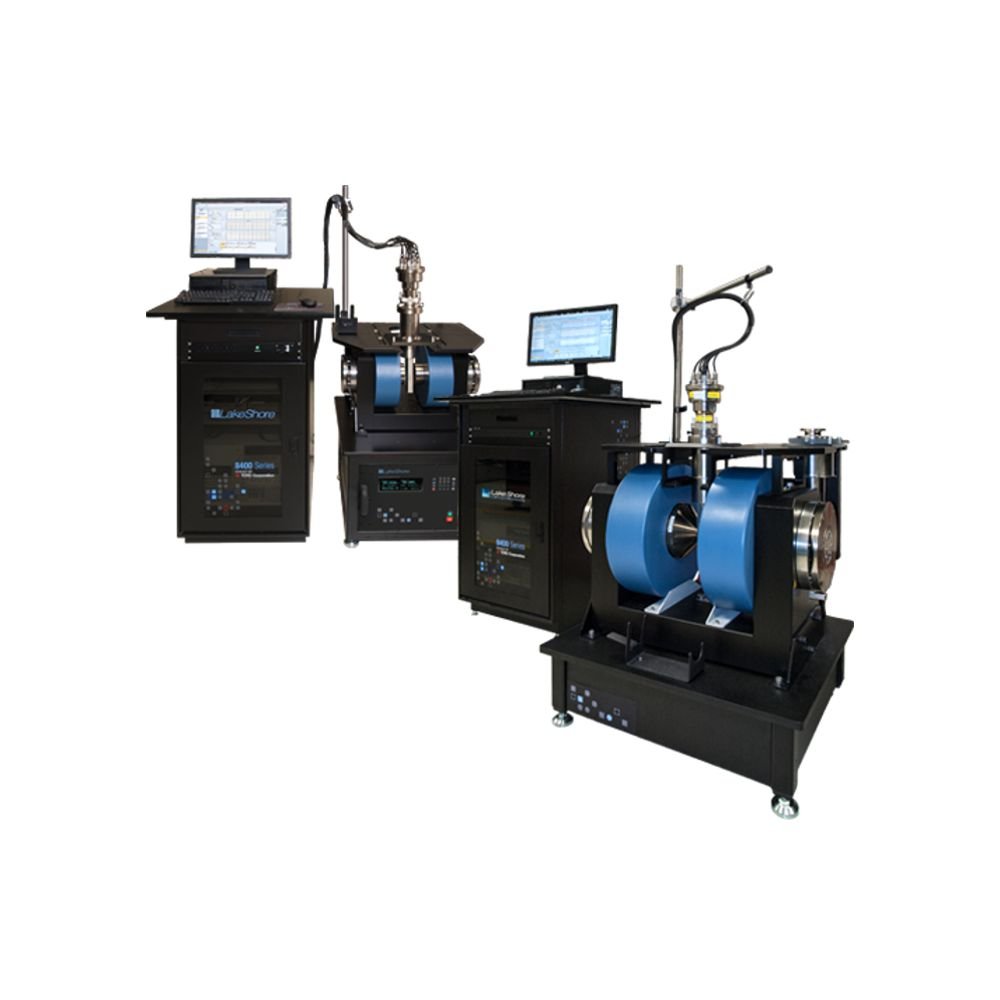
8400 Series HMS
Lake Shore
The Lake Shore 8400 Series can be used with both DC and AC field Hall measurement methodologies to facilitate the broadest range of research applications. The system includes fully integrated instrumentation, a magnet and power supply, plus software that dramatically helps you increase your research productivity and provides results that you can trust.When used with the AC field measurement option, the system is ideal for use with emerging class of materials that typically have mobilities below 1 cm2/V s—the types of materials with electronic properties that can be difficult or impossible to measure with traditional DC field Hall methods. These include many contemporary semiconductor and electronic materials, such as photovoltaic (solar cell) and thermoelectric materials, new display technologies, and organic electronics.
The standard system is capable of DC field measurements and has a resistance range from 0.5 mΩ to 10 MΩ. Measure Hall voltage, Hall coefficient, Hall mobility, and resistivity. With options added, the system allows you to measure down to 0.5 µΩ and as high as 200 GΩ in DC fields. You can also determine carrier density and carrier mobility versus temperature.
For temperature-dependent applications, the 8400 Series options enable you to measure samples from 15 K to 1273 K with a closed-cycle refrigerator and high-temperature oven, or take dedicated 77 K measurements with an optional single-point LN 2 body.
The 8400 Series HMS provides a robust platform that can be configured to meet your specific needs and supports the addition of new features as your material measurement needs evolve. An assortment of options including variable temperature assemblies, high and low resistance, and optical access broaden your measurement opportunities and simplify experimental processes.
Features of the 8400 Series
•Ideal for variable temperature measurement and mobilities from 1 to 106 cm2/V s
•Optional AC field extends mobility measurement range down to 10-3 cm2/V s
•Maximum DC fields to 1.67 T (8404) and 2.25 T (8407)
•Optional AC fields to 1.18 T (8404) and 1.31 T (8407)
•Standard resistance range of 0.5 mΩ to 10 MΩ
•High resistance option widens range to 200 GΩ
•Low resistance option significantly reduces resistance noise floor
•Temperatures from 15 K to 1273 K
| Pole cap (in) | Air gap (in) | DC (T) | AC RMS (T) | ||
| Model 8404 | At room temperature | 2 (standard) | 1 | 1.67 | 1.18 |
| 4 (optional) | 1 | 1.35 | 0.95 | ||
| With variable temperature option | 2 (standard) | 2 | 0.89 | 0.63 | |
| 4 (optional) | 2 | 0.88 | 0.62 | ||
| Model 8407 | At room temperature | 4 (standard) | 1 | 2.10 | 1.20 |
| 2 (optional) | 1 | 2.25 | 1.31 | ||
| With variable temperature option* | 4 (standard) | 2 | 1.45 | 0.69 | |
| 2 in pole caps not recommended for use with variable temperature in the 8407 | |||||
8400 Series Specifications
| 8404 | 8407 | |||||||||||||||||||
| DC | AC | DC | AC | |||||||||||||||||
| Measurement specifications | ||||||||||||||||||||
| Mobility | 1 to 1 × 106 cm2/v s | 1 × 10⁻³ to 1 × 106 cm2/v s | 1 to 1 × 106 cm2/v s | 1 × 10⁻³ to 1 × 106 cm2/v s | ||||||||||||||||
| Carrier concentration density | 8 × 10² to 8 × 1023 cm-3 | 8 × 10² to 8 × 1023 cm-3 | ||||||||||||||||||
| Resistivity | 1 × 10⁻⁵ to 1 × 10⁵ Ω·cm | 1 × 10⁻⁵ to 1 × 10⁵ Ω·cm | ||||||||||||||||||
| Electronic specifications* | ||||||||||||||||||||
| Standard resistance range |
±0.5% rdg ±0.5% range: ±0.075% rdg ±0.05% range: |
VdP/Hall bar: 0.5 mΩ to 10 MΩ 300 nV RMS noise floor for sample resistances up to 100 Ω; |
±0.5% rdg ±0.5% range: ±0.075% rdg ±0.05% range: |
VdP/Hall bar: 0.5 mΩ to 10 MΩ 300 nV RMS noise floor for sample resistances up to 100 Ω; |
||||||||||||||||
| Optional high resistance configuration |
±0.25% rdg: ±1.5% rdg: ±5% rdg: |
VdP/Hall bar: 10 kΩ to 8 GΩ <1250 nV RMS noise floor for |
±0.25% rdg: ±1.5% rdg: ±5% rdg: |
VdP/Hall bar: 10 kΩ to 8 GΩ <1250 nV RMS noise floor for |
||||||||||||||||
| Optional low resistance configuration |
For resistance larger than 10 Ω, the voltage noise floor is independent of current for currents less than 1 mA. |
NA |
For resistance larger than 10 Ω, the voltage noise floor is independent of current for currents less than 1 mA. |
NA | ||||||||||||||||
| Current | ±1 pA to ±100 mA | ±1 pA to ±100 mA | ||||||||||||||||||
| Compliance voltage | 100 V | 100 V | ||||||||||||||||||
| Environment | ||||||||||||||||||||
| Room temperature field** (25 mm [1 in] airgap) |
1.67 T with standard 50 mm (2 in) pole caps 1.35 T with optional 100 mm (4 in) pole caps |
1.18 T with standard 50 mm (2 in) pole caps 0.95 T with optional 100 mm (4 in) pole caps |
2.10 T with standard 100 mm (4 in) pole caps 2.25 T with optional 50 mm (2 in) pole caps |
1.20 T with standard 100 mm (4 in) pole caps 1.31 T with optional 50 mm (2 in) pole caps |
||||||||||||||||
| Variable temperature field** (50 mm [2 in] airgap) |
0.89 T with standard 50 mm (2 in) pole caps 0.88 T with optional 100 mm (4 in) pole caps |
0.63 T with standard 50 mm (2 in) pole caps 0.62 T with optional 100 mm (4 in) pole caps |
1.45 T with standard 100 mm (4 in) pole caps |
0.69 T with standard 100 mm (4 in) pole caps |
||||||||||||||||
| Optional AC field frequency ranges | NA | 0.05 and 0.1 Hz | NA | 0.05 and 0.1 Hz | ||||||||||||||||
| Sample size | Up to 10 mm × 10 mm × 3 mm standard, up to 50 mm diameter × 3 mm optional |
Up to 10 mm × 10 mm × 3 mm standard, up to 50 mm diameter × 3 mm optional |
||||||||||||||||||
| Standard module temperature | Room temperature | Room temperature | ||||||||||||||||||
| Single point LN2 option temperature | 77 K point | 77 K point | ||||||||||||||||||
| CCR option temperature | 15 K to 400 K with standard CCR, 15 K to 350 K with optical CCR | 15 K to 400 K with standard CCR, 15 K to 350 K with optical CCR | ||||||||||||||||||
| Oven option temperature | Room temperature to 1,273 K; at 773 K and ±1% rdg: maximum = 1 MΩ; at 1,273 K and ±1% rdg: maximum = 1 kΩ |
Room temperature to 1,273 K; at 773 K and ±1% rdg: maximum = 1 MΩ; at 1,273 K and ±1% rdg: maximum = 1 kΩ |
||||||||||||||||||
| Magnet | ||||||||||||||||||||
| Pole diameter | 4 in | 7 in | ||||||||||||||||||
| Pole cap diameter | 50 mm (2 in) standard, 100 mm (4 in) optional | 100 mm (4 in) standard, 50 mm (2 in) optional | ||||||||||||||||||
| Air gap at room temperature | 25 mm (1 in) | 25 mm (1 in) | ||||||||||||||||||
| Air gap with variable temperature options | 50 mm (2 in) | 50 mm (2 in) | ||||||||||||||||||
| Field uniformity |
25 mm (1 in) air gap, 50 mm (2 in) pole caps: ±0.35% over 1 cm3 (0.4 in3) |
25 mm (1 in) air gap, 50 mm (2 in) pole caps: ±0.35% over 1 cm3 (0.4 in3) 25 mm (1 in) air gap, 100 mm (4 in) pole caps: ±0.05% over 1 cm3 (0.4 in3) 50 mm (25 in) air gap, 100 mm (4 in) pole caps: ±0.15% over 1 cm3 (0.4 in3) |
||||||||||||||||||
| Cooling (magnet and power supply) | 7.6 L/min (2 gal/min), 10.3 L/min (2.7 gal/min) with CCR option | 19 L/min (5 gal/min), 23 L/min (6 gal/min) with CCR option | ||||||||||||||||||
| 3-phase bipolar magnet power supply | ||||||||||||||||||||
| Maximum output | ±35 V ±70 A (2.5 kW) | ±75 V ±135 A (9.1 kW) | ||||||||||||||||||
| Utilities | ||||||||||||||||||||
| Total system cooling water power dissipation (50 or 60 Hz) — see list of available recirculating chillers | 4.25 kW; 7.45 kW with optional CCR | 13.4 kW; 16.6 kW with optional CCR | ||||||||||||||||||
*Probe contact resistance may vary with sample
**All field values are nominal and can vary ±1%.
8400 Series Hardware
| T E M P E R A T U R E O P T I O N S | ||||
| Standard room temperature | Model 84015 77 K LN2 body option | Model 84016 CCR option |
Model 84017 oven option |
|
| Standard insert | Standard with system |
Used together |
- | - |
| Standard body | Standard with system |
- | - | - |
| Optical access body | 84006, requires 84060 |
- | 84016-O, requires 84060 |
- |
| Sample rotation | 84010 |
84010 |
Standard with 84016 |
Standard with 84017 |
| Sample mounting kit Five 10 mm solder cards, one with PT sensor, wire and foil |
Standard with system |
840930 |
- | - |
| Sample card kit Five 10 mm solder cards |
840931 |
840931 |
- | - |
| Sample card kit Five 10 mm solder cards with PT sensors |
840932 |
840932 |
- | - |
| 10 mm prober pin sample card with PT sensor |
840910 |
840910 |
- | - |
| 50 mm prober pin sample card with PT sensor |
840911 |
- | - | - |
| Temperature monitoring | 841-STM or 840-VTA* |
841-STM or 840-VTA* |
- | - |
| Variable temperature | - | - | 840-VTA |
840-VTA |
| Pump | Not required |
Not required |
TPS-FRG or equivalent |
E2M or equivalent |
| Chiller for electromagnet | Not applicable |
Not applicable |
||
| Floor mount hardware | 840950 |
Not applicable |
Not applicable |
Not applicable |
| High uniformity | 8404: EM4-4PB |
8404: EM4-4PB |
8404: EM4-4PB |
8404: EM4-4PB |
8400 Series measurements
|
|
*Limits maximum resistance to 8 GΩ


