FP Series Hall Probes
Lake Shore
The FP Series probes make it easier than ever to integrate magnetic field measurement into your system. Take advantage of probes and sensors that really fit your application for optimum measurement results.
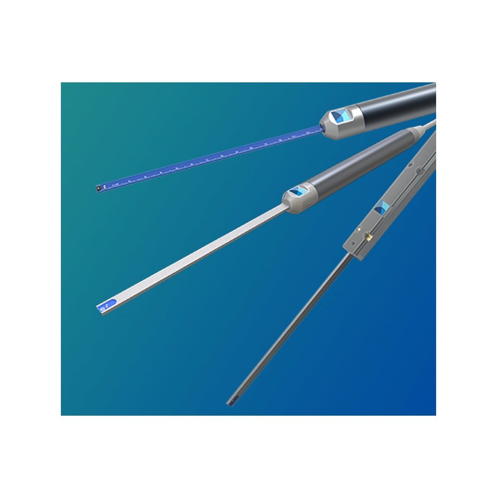
Lake Shore offers probes for every need, including 3-axis (vector), transverse, and axial models available in both handheld and fixture-mountable versions. Special cryogenic versions are also available.
If your application is unique, Lake Shore may be able to design a probe to fit your exact needs. FP Series probes are all manufactured in our Ohio facility with engineering staff on site ready to support your application. Contact your local sales representative today to start the conversation.
specific probe customization availableFP Series Hall probe features
- Wide field range—suited for everything from earth-field to the world’s strongest electromagnets
- 2Dex™ sensors with tiny active area of just 0.1 mm2 for more precise measurements
- Temperature and linearity (field) compensation are built-in
- Versatile handle and stem options to suit numerous applications
- Ease of use features such as active area and polarity indicators
- Application-specific probe customization available
FP Series probe specifications
Sensor type
|
|
Sensor |
Description |
Active area |
|
2X-250 |
2Dex™ 2X-250 |
2Dex™ standard sensor |
0.1 mm2 |
Temperature compensation
|
|
Built-in thermistor |
Temperature range |
|
Standard |
Yes |
0 °C to 90 °C |
|
Flexible-thin |
Yes |
0 °C to 90 °C |
|
Cryogenic |
No |
1 K to 400 K using external temperature data |
Stem material
|
|
3-axis |
Transverse |
Axial |
|
Standard |
Anodized aluminum tube with a 4 mm square cross section |
Anodized aluminum tube with a 1.55 mm maximum thickness by 4.57 ±0.13 mm rectangular cross section |
Anodized aluminum tube with a 2 mm diameter circular cross section |
|
Flexible-thin |
NA |
FR-4 PCB 1.14 mm maximum thickness by 3.53 mm |
NA |
|
Cryogenic |
NA |
316 stainless steel tube with 4.75 +0.15/-0.11 mm diameter circular cross section |
316 stainless steel tube with 4.75 +0.15/-0.11 mm diameter circular cross section |
Stem length
|
Distance from tip of sensor to beginning of handle |
Stem operating temperature range
|
|
3-axis |
Transverse |
Axial |
|
Standard |
0 °C to 90 °C |
0 °C to 90 °C |
0 °C to 90 °C |
|
Flexible-thin |
NA |
0 °C to 90 °C |
NA |
|
Cryogenic |
NA |
1.5 K to 363 K |
1.5 K to 363 K |
Handle
|
|
Handheld (default) |
Mountable |
|
Length, including strain relief |
138 mm |
110 mm |
|
Diameter |
13 mm |
NA |
|
Thickness |
NA |
10 mm |
|
Width |
NA |
12 mm |
|
Material |
ABS/polycarbonate blend with anodized aluminum grip |
Machined aluminum with brass screws. Mountable to fixture using customer supplied M2 screws with 3.8 mm diameter socket head and 2 mm diameter alignment pins |
|
Operating temperature range |
0 °C to 80 °C |
0 °C to 80 °C |
Cable
|
|
Single-axis |
3-axis |
|
Diameter |
4 mm (0.17 in) |
5.2 mm (0.21 in) |
|
Bend radius |
40 mm (1.57 in) |
52 mm (2.05 in) |
|
Operating temperature range |
-40 °C to 80 °C |
|
|
Conductors |
4 twisted-pair |
8 twisted-pair |
|
Cable shield |
100%-coverage foil |
|
|
Cable insulation |
Modified polyphenylene ether |
|
|
Connector |
26-pin Mini-D with quick-release latch |
|

Probe configuration options
Customize your probe using the range of available options to match your application.
FP-aa-bbb-cd ee(f)(-gg)
Sensor
|
2X-250 |
2Dex™ |
Sensor
|
2X-250 |
2Dex™ |
2Dex™ sensors are currently the only sensor types currently available with FP Series probes. These are the first probes to feature 2Dex sensors which offer a great balance of sensitivity, linearity, stability and ruggedness. These sensors set the new standard for the majority of field measurement applications.
Orientation
|
Z |
3-axis |
|
T |
Transverse (single-axis) |
|
A |
Axial (single-axis) |
Orientation
Hall sensors are inherently directional, so the anticipated field direction will guide the selection of probe orientation.
|
Z |
3-axis |
Multiple sensors are placed to measure three orthogonal field vectors, allowing the measurement of both the overall field value and direction. This is particularly useful in several scenarios:
- Complex fields where the field direction is not known or changing over time
- Quick handheld measurements
- Field mapping of a volume
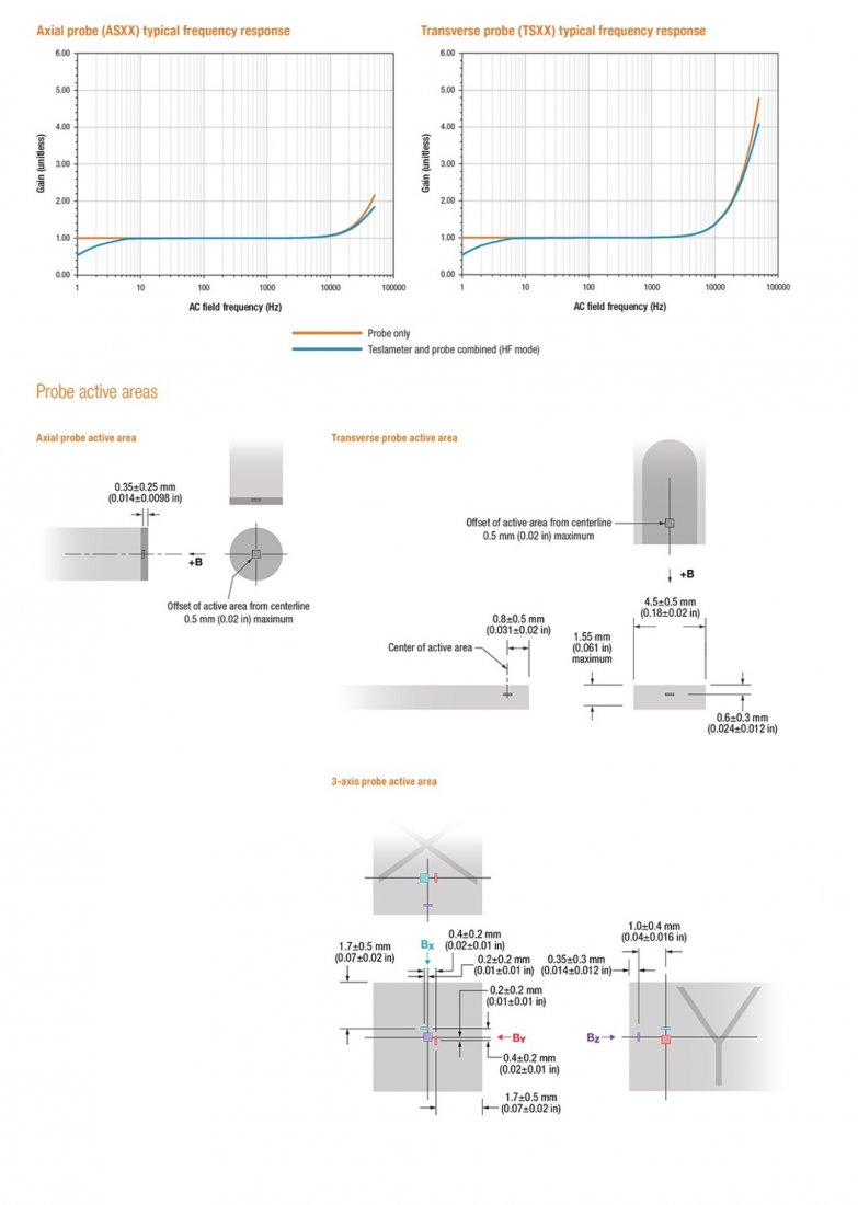
The three individual sensors don’t occupy the exact same location, meaning the three separate measurements are for slightly different positions in space. This results in the specification of an active volume, as opposed to an active area for single-axis probe variants. These probes can be identified by their square stem cross-section.
3-axis probes are only available with a standard stem up to 30 cm in length.
|
T |
Transverse (single-axis) |
The sensor is positioned to measure fields running perpendicularly through the probe stem. This is most useful for measuring fields inside magnet gaps. These probes are easily identified by their flattened rectangular stem.
|
A |
Axial (single-axis) |
The sensor is placed very near to the tip of the probe and aligned to measure fields normal to the tip of the probe. This orientation is necessary when measuring inside solenoids, and can be useful for measuring fields at magnet poles due to the increased ease of alignment and fine adjustment.
Axial probes are not offered with a flexible-thin stem.
Stem type
|
S |
Standard |
|
F |
Flexible-thin |
|
C |
Cryogenic |
Stem type
The sensor/s are housed in stem types suited for various applications. Where possible, active area locations are marked on the stems.
|
S |
Standard |
The general-purpose stem options offer an excellent balance of size and strength. Constructed from extruded and precision machined aluminum, these stems will be the superior choice in most situations.
|
F |
Flexible-thin |
This stem type is currently only available as a transverse orientation option at a fixed stem length. The surrounding aluminum stem of the standard probe is removed, exposing the PCB and sensor element. This results in a somewhat flexible stem that is also thinner than the standard offering, making it the best probe for measuring in very thin magnet gaps. It is possible to snap the PCB stem of this probe with excessive bending, so this should be minimized to prolong the life of the probe.
This stem also features a helpful ruler printed directly on the PCB. Useful in determining just how far the probe has been inserted into the magnet gap.
|
C |
Cryogenic (coming soon) |
Ultra-low temperature applications require a more drastic overhaul of the probe stem:
- Non-magnetic stainless-steel alloy minimizes heat leak, while providing strength
- Greater stem lengths offered as standard to reach into the cryogenic environment
- Vented at the tip to allow cryogens to escape safely
- Cryogenic 2Dex™ sensors used in place of standard solution
Due to the increased sensor size used in these probes, 3-axis probes with very small active volumes are not possible. Contact us if you have an application that requires multi-axis cryogenic measurements to discuss options.
Stem length
|
05 |
5 cm (2 in) |
|
15 |
15 cm (6 in) |
|
30 |
30 cm (12 in) |
|
150 |
150 cm (60 in) |
Stem length
FP Series probes come in various lengths to suit your application.
|
|
5 cm (~2 in) |
15 cm (~6 in) |
30 cm (~12 in) |
150 cm (~60 in) |
|
|
05 |
15 |
30 |
150 |
|
Standard |
? |
? |
? |
|
|
Flexible |
|
? |
|
|
|
Cryogenic |
|
|
? |
? |
If your application requires a non-standard stem solution, please contact us to discuss options.
Special handle (optional)
|
|
Handheld (default) |
|
M |
Mountable |
Special handle (optional)
Both handle options include polarity indicators when ordered with a transverse orientation, making it easy to quickly determine whether a magnet polarity has been switched, or if the probe is just being held incorrectly.
|
|
Handheld (default) |
The default handle configuration is deigned to be a comfortable and functional handheld solution with an anodized aluminum grip for a solid and long-lasting grip surface.
|
M |
Mountable |
In situations where probe fixturing is required to achieve repeatable measurements, the mountable form factor features a flat machined aluminum surface. It also includes locating pinholes for precise probe alignment and is easily held in place with just two screws.
Publicly available drawings and CAD models for this handle will make integration with your hardware quick and easy while minimizing the risk of a design error. These handles are available with standard and flexible stem choices.
Cryogenic probes are not available with a mountable stem.
Additional cable length (optional)
|
|
2 m (6 ft) (default) |
|
6 |
6 m (20 ft) |
|
15 |
15 m (50 ft) |
Additional cable length (optional)
|
2 m (6 ft) |
6 m (15 ft) |
15 m (50 ft) |
|
|
6 |
15 |
The probe cable and connector have also received close attention to optimize performance and usability. The shielded cable was selected to be as thin and light as possible, while using a special insulation that is both recyclable and forms a part of the TruZero™ technology that allows the probes to operate without needing to zero.
The connector makes use of the compact Micro-D standard to support all connections required for a 3-axis probe in a reasonably sized package. Both single and multi-axis probes use this connector, so there is no need to pay special attention to making individual axis connections as is the case for other multi-connector solutions. A user-friendly latching mechanism means swapping probes is fast and trouble free and can be accomplished in just a few seconds.
Calibration data for the probe is stored inside the connector, allowing for fast and simple probe swapping. The teslameter configures itself automatically each time a probe is connected.
All probes come with a standard 2 m (6 ft) cable, but can be customized with either a 6 m (20 ft) or 15 m (50 ft) cable if you require more distance between your teslameter and field source. This is particularly important for very large fields, as the teslameter unit itself should not be exposed to strong fields.
FP Series probe availability
Transverse |
Stock probes |
|
|
||||||
|
Stem type |
Stem material |
Stem size |
Form factor |
Stem lengths (cm) |
Part number |
Available |
|||
|
Standard |
Aluminum |
1.55 × 4.57 mm |
Handheld |
5 |
15 |
30 |
— |
FP-2X-250-TSXX |
Now |
|
Mountable |
5 |
15 |
30 |
— |
FP-2X-250-TSXXM |
Now |
|||
|
Flexible-thin |
PCB |
1.14 × 3.53 mm |
Handheld |
— |
15 |
— |
— |
FP-2X-250-TF15 |
Now |
|
Mountable |
— |
15 |
— |
— |
FP-2X-250-TF15M |
Now |
|||
|
Cryogenic |
Stainless steel |
4.75 mm diameter |
Handheld |
— |
— |
30 |
150 |
FP-2X-250-TCXXX |
Coming soon |
Axial |
|||||||||
|
Stem type |
Stem material |
Stem size |
Form factor |
Stem lengths (cm) |
Part number |
Available |
|||
|
Standard |
Aluminum |
2 mm diameter |
Handheld |
5 |
15 |
30 |
— |
FP-2X-250-ASXX |
Now |
|
Mountable |
5 |
15 |
30 |
— |
FP-2X-250-ASXXM |
Now |
|||
|
Cryogenic |
Stainless steel |
4.75 mm diameter |
Handheld |
— |
— |
30 |
150 |
FP-2X-250-ACXXX |
Coming soon |
3-axis |
|||||||||
|
Stem type |
Stem material |
Stem size |
Form factor |
Stem lengths (cm) |
Part number |
Available |
|||
|
Standard |
Aluminum |
4 mm × 4 mm |
Handheld |
5 |
15 |
30 |
— |
FP-2X-250-ZSXX |
Now |
|
Mountable |
5 |
15 |
30 |
— |
FP-2X-250-ZSXXM |
Now |
|||
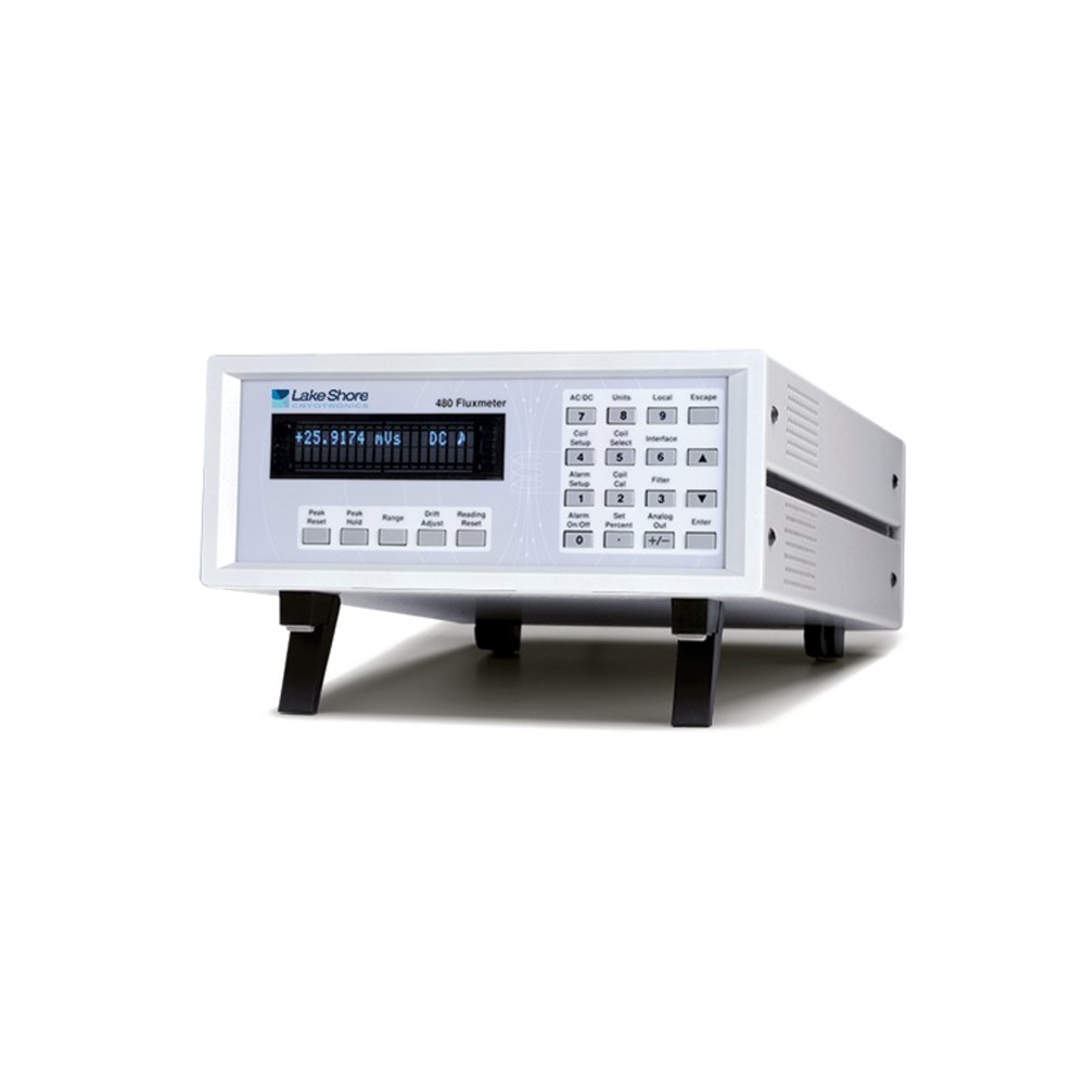
1 - Model 460 Fluxmeter

An advanced tool designed primarily for use in industrial and measurement systems settings, the Model 480 fluxmeter measures total flux from which B, flux density, and/or H, magnetic field strength, can be determined. The Model 480 is valuable for magnetizing, manual and automated magnet testing and sorting, and as the main component in BH loop or hysteresis measurement system applications. The Model 480 fluxmeter is compatible with most sensing coils and fixtures. More information on the Model 480 fluxmeter...
- Manual magnet testing
- Automated magnet testing
- Magnetizing
- Materials analysis
- AC magnetic fields
- Drift adjustment
- Model 480 rear panel
- Display
- Helmholtz and search coils
Model 480 Features
- 5¾ digit DC resolution (1 part out of ±300,000)
- Automatic drift compensation
- Very fast peak capture
- AC frequency response to 50 kHz
- IEEE-488 and serial interfaces
- Storage of parameters for up to 10 existing coils
Specifications
Measurement
Number of units: 1
Input type: 2-lead, ground referenced
Input resistance: 100 kΩ or 10 kΩ
Maximum operating input voltage: 60 V
Absolute maximum input voltage: 100 V — WARNING — voltages between 60 V and 100 V will not damage the instrument but could result in personal injury or damage to other instruments
Update rate: 5 rdg/s display; 30 rdg/s IEEE-488; 30 rdg/s serial
DC
DC resolution: To 5¾ digits
DC integrator capacitance: 1 µF nominal
DC input resistance: 100 kΩ 10 kΩ
DC ranges: 300 mVs, 30 mVs, 30 mVs, 3 mVs
DC resolution: 0.001 mVs, 0.0005 mVs, 0.0005 mVs, 0.0005 mVs
DC accuracy: Offset: ±10 µVs ±DC integrator drift; Gain: ±0.25% of reading (<10 Vs/s maximum rate of change)
DC minimum dΦ/dt: 20 µVs/min
DC maximum dΦ/dt: 60 Vs/s
DC integrator drift: ±1 µVs/min, 0.0004% FS/min on 300 mVs range (100 kΩ input resistance constant temperature environment)
DC peak
DC peak resolution: 4¾ digits
DC peak integrator capacitance: 1 µF nominal
DC peak input resistance: 100 kΩ 10 kΩ
DC peak ranges: 300 mVs, 30 mVs, 30 mVs, 3 mVs
DC peak resolution: 0.01 mVs, 0.001 mVs, 0.001 mVs, 0.001 mVs
DC peak minimum reading: 0.05 mVs, 0.005 mVs, 0.005 mVs, 0.005 mVs
DC peak accuracy: Offset: ±100 µVs ±DC integrator drift; Gain: ±5% of reading (<10 Vs/s maximum rate of change)
DC peak maximum dF/dt: 60 Vs/s
DC peak update rate: Reduces update rate to ¼ normal
AC
AC resolution: 4¾ digits (reduced to 3¾ digits on the 30 µVs range)
AC integrator capacitance: 0.1 µF nominal
AC input resistance: 100 kΩ
AC ranges: 30 mVs, 3 mVs, 300 µVs, 30 µVs
AC resolution: 0.001 mVs, 0.0001 mVs, 0.01 µVs, 0.01 µVs
AC minimum rdg: 3.000 mVs, 0.3000 mVs, 30.00 µVs, 3.00 µVs
AC frequency response: 2 Hz to 50 kHz
AC accuracy: ±1% rdg ±10 µVs (10 Hz to 10 kHz sinusoidal); ±5% rdg ±10 µVs (2 Hz to 50 kHz sinusoidal)
AC integrator drift: NA
AC peak
AC peak resolution: 3¾ digits
AC peak integrator capacitance: 0.1 µF nominal
AC input resistance: 100 kΩ
AC peak ranges: 30 mVs, 3 mVs, 300 µVs
AC peak resolution: 0.01 mVs, 0.001 mVs, 1 µVs
AC minimum reading: 0.01 mVs, 0.001 mVs, 5 µVs
AC peak accuracy: ±5% rdg ±10 µVs (10 Hz to 10 kHz sinusoidal); ±10% rdg ±10 µVs (2 Hz to 50 kHz sinusoidal)
AC peak update rate: Reduces update rate to ¼ normal
Front panel
Display type: 2-line × 20-character, vacuum fluorescent display
Display resolution: To ±5¾ digits
Display update rate: 5 rdg/s
Display units: Vs, MxN, WbN, VF, MxF, WbF, G, T, Wbcm, A, %
Units multipliers: p, n, µ, m, k, M, G
Annunciators: AC – AC input signal, DC – DC input signal, ∧ ∨ – Positive and negative peaks, R – Remote operation, :Alarm on
Keypad: 21 full travel keys
Interfaces
IEEE-488.2 capabilities: SH1, AH1, T5, L4, SR1, RL1, PP0, DC1, DT0, C0, E1
Serial interface: RS-232C electrical, DA-9 connector, 9600 BAUD
External reset type: Contact closure
Software support: LabVIEW™ driver
Alarms
Number: 2
Settings: High and low set point, Inside/Outside, Audible
Actuators: Display annunciator, beeper, relays
Relays
Number: 3
Contacts: Normally open (NO), normally closed (NC), and common (C)
Contact rating: 30 VDC at 2 A
Operation: Follow high, low alarms with third relay indicating no alarm state — can be operated manually
Connector: Detachable terminal block
Monitor analog output
Scale: ±3 V = ±FS on Vs range
Accuracy: ±1% of reading ±10 mV, (DC to 10 kHz); ±5% of reading ±10 mv, (10 kHz to 50 kHz)
Minimum load resistance: 1 kΩ
Connector: Detachable terminal block
Corrected analog output
Scale: User selected
Range: ±10 V
Resolution: 0.3 mV
Accuracy: ±2.5 mV
Minimum load resistance: 1 kΩ
Connector: Detachable terminal block/p>
General
Ambient temperature: 15 ºC to 35 ºC at rated accuracy; 5 ºC to 40 ºC with reduced accuracy
Power requirement: 100, 120, 220, 240 VAC, +5%, -10%, 50 or 60 Hz, 20 VA
Size: 216 mm W × 89 mm H × 318 mm D (8.5 in × 3.5 in × 12.5 in), half rack
Weight: 3 kg (6.6 lb)
Approval: CE mark, RoHS


